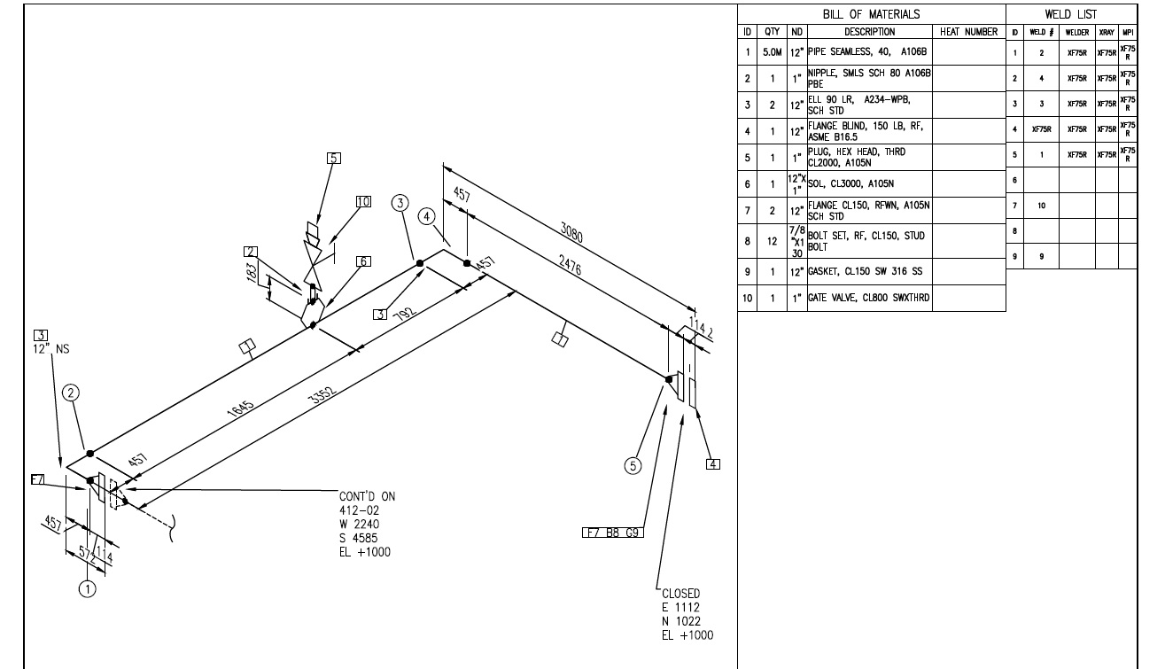

Isometrics are usually drawn from information found on a plan and sectional elevation views. Unlike orthographic drawings, piping isometric drawings allow the pipe line to be drawn in a manner by which the length, width and depth are shown in a single view. Sectional views are required for clarity of pipe routing More number of drawings needed in orthographic views than ISO to represent the same piping system. In a orthographic view it is not a problem if the pipe runs in one plane, but when a pipe runs in two or three planes (north to south, then down and then to the west, etc.) an orthographic view can be unclear. Simplicity (Only one pipe line is drawn in one A3 size paper). Also pipe fabricator can pick up material required for fabrication of pipe line from stores, with the help of Bill of Material given in isometric drawing. A pipe fabricator can read the drawing and understand pipe routine easily. An isometric drawing is generally on a A3 size paper. To aid pipe fabricator on site, isometric drawings are prepared. But 3D scale model can not be put on a paper, and 3D scale model does not indicate dimensions. A pipe fabricator can understand GA drawing better only with the help of 3D scale model. A0 or A1 size drawing is to big to handle. A GA drawing is generally on A0 or A1 size paper and contains a lot of lines, and may not be easy to understand pipe routine. 2D General Arrangement (GA) drawings are used for fabrication on site. This is then converted into a 3D scale model, to check interference of pipe lines.

In this all pipelines are drawn at zero z co-ordinate. Just as an apple can be sectioned any way you choose, so can an object in a sectional view of a drawing or sketch.Why Isometric Drawings are required?: Generally in the development of a project, a conceptual 2D drawing is first created. When you cut an apple in half you have sectioned it. In this example, blocks A and B result after the block in figure 1 has been “Sectioned”.

Sectioning is used frequently on a wide variety of Industrial drawings. The process of sketching the internal configuration of an object by showing it cut apart is known as sectioning. In that way, the many hidden lines on the sketch are eliminated. When an object becomes more complex, as in the case of an automobile engine block, a clearer presentation of the interior can be made by sketching the object as it would look if it were cut apart. You have learned that when making a multiview sketch, hidden edges and surfaces are usually shown with hidden (dash) lines.


 0 kommentar(er)
